How to set up a proof of concept Wi-Fi mesh network
May 23, 2025 by Killian Otto | 2754 views
https://cylab.be/blog/416/how-to-set-up-a-proof-of-concept-wi-fi-mesh-network
Introduction
This blog post explains how to set up a Wi-Fi mesh network based on pre-defined architecture composed of hardware and software components.
These components aren’t a fatality, they have been chosen/implemented by facility or because some limitations appeared, they can be potentially replaced by other alternatives.
An aspect that this blog post takes in consideration is that the architecture on which the project is based is that this one must be deployed in some kind of environments where resources such electricity and internet for example are limited.
Important fact to notice is that this blog post voluntary doesn’t expose any IP and MAC addresses, if some element would look as lacking on some figures it’s normal.
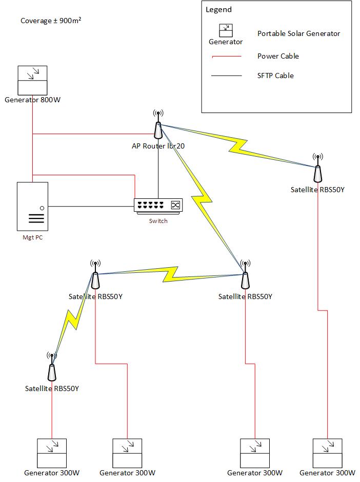 Figure 1. Architecture on which the Wi-Fi mesh network is based.
The hardware components of the infrastructure :
- Generator 300W as Mobisun Pro Air battery pack with solar panel integrated
- Switch as a FS S3900-24T4S switch
- Mgt PC as an Ubuntu server
- AP Router Ibr20 as a NETGEAR WAX610
- Satellite RBS50Y as a NETGEAR WAX610Y
Warning : In this architecture we work on the assumption that the internet connection (WAN) and the switch are already deployed.
The Mgt PC is a server that host the software components of the architecture, it hosts a pfsense as the firewall of the architecture and monitoring tools such as security onion and checkmate.
The AP Router Ibr20 on the figure 1 constitutes the entry point of the Wi-Fi mesh network, it means that its the node connected to the switch used to spread the initial Wi-Fi (mesh) signal across the other nodes of the Wi-Fi mesh network.
The Satellite RBS50Y are the nodes used to spread the Wi-Fi (mesh) signal over large areas, depending on how they’ve been configured they should be able to communicate between each other to allow a frame/packet to reach a destination.
The order how each sections of the blog post are describe to set up the architecture isn’t a mandatory order, they can variate depending on your need.
What is a Wi-Fi mesh network ?
The title of this blog post is How to set up a Wi-Fi mesh network, I made an introduction about the project and it’s architecture but I didn’t explain what’s a Wi-fi mesh network.
(Before creating one it could be interesting to know what it is and it works.)
A mesh network is a type of local area network (LAN) composed of multiple nodes that work together to broadcast a Wi-Fi signal over a large area.
Each nodes that compose this networks can relay data to other nodes in the network, passing it along until it reaches its destination.
The main differences between an extend network (that use an extender) is that with this one broadcast a single Wi-Fi signal. Another difference with a traditional wireless networks is that here each device isn’t necessary connected to a central router.
Hardware requirements for the server
As mentioned above the server hosts the software components of the architecture, each of them have specific minimum hardware requirements that I’m going to detail.
Pfsense
The minimum resource requirements for this one are :
- CPU : 64-bit or amd64 (x86-64) CPU
- RAM : 1GB
- Storage : 8GB
- NICs : 2
Security Onion
The second is security onion that will be installed with a StandAlone installation, for this one here are the necessary hardware requirements :
- CPU : 6-14 CPUs (These can variate depending on the numbers of plugins added)
- RAM : 16-128 GO for a medium network, it is recommended to have 24 GO when small piece of the network must be analyzed.
- STORAGE : 1TB and 80 Go to 108TB, these estimations include the storage for the operating system and data collected.
- NICs : 2
Medium network means a network with a bandwidth of 100MBs-1GBs.
Checkmate
Checkmate is runs by containers, there isn’t real requirements about it but here is some estimations:
For example if you have 300 monitors, you’ll need 3Gb of disk space each month if they are configured to check in 1 sec periods (intervals) it means that you’ll need 36Gb of disk for the entire year to monitor 300 servers.
Warning the server needs to have 3 physical network interfaces !
This is due to the fact that the pfsense is pretty sensitive, last one needs a NIC for the LAN and the WAN network.
Configuration of the server
This section and sub-sections explains how to install and configure the server and its components.
Installation of the operating system
Ubuntu 24.04.1 LTS is the OS that had been installed on the server during the implementation of the architecture, the ISO had been push on a bootable USB stick. To do that an ISO of Ubuntu server must be downloaded, Banela Etcher had been use to make the USB stick bootable.
To perform it you just have to install Banela Etcher, running it, selecting your ISO of Ubuntu server and your USB key you want to make bootable and click on Flash. Once done you just have to plug the usb key on the server boot on it.
The documentation of the installation of the OS itself will not be documented here, the installation has nothing particular, you just need to notice you must create bond on your 3 network interfaces.
It is necessary to create bonds for each network interfaces (3) on the server, a network bond is a method to combine or aggregate physical and virtual network interfaces to provide a logical interface with higher throughput or redundancy.
Installation and configuration of KVM
KVM (Kernel-based Virtual Machine) is an open source virtualization technologies that is used in this architecture to host some components such as pf-sense and security onion.
To begin execute the following command to install all required packages for a successful installation :
sudo apt install -y qemu-kvm libvirt-daemon libvirt-clients bridge-utils libvirt-daemon-system
Once installed libvirtd daemon must be enabled and started by executing the following commands :
sudo systemctl enable --now libvirtd
sudo systemctl start libvirtd
You can check the status of the daemon with the following command :
sudo systemctl status libvirtd
After that you will also need to add the user of the server to the kvm and libvirt group of the server by executing the following command:
sudo usermod -aG kvm $USER
sudo usermod -aG libvirt $USER
To apply this change you’ll need to log out and sign in to your user account.
And finely you will need to create a Network Bridge interface to get access to KVM virtual machine outside of your Ubuntu 22.04.
To map VM’s interface named (virbr0) to a network bridge that will be created automatically by KVM you will need to edit the .yaml file config of the network interface(s) located in the /etc/netplan or create one (01-netcfg.yaml) in.
Once done the modifications can be applied by executing the following command :
sudo netplan apply
Installation of cockpit
To install cockpit on the server the following commands must be executed :
sudo apt update
. /etc/os-release
sudo apt install -t ${VERSION_CODENAME}-backports cockpit
sudo apt install cockpit-machines
When done you can access to cockpilot web portal/interface via the following URL in your web-browser :
https://IP_ADDRESS_OF_MACHINE:9090
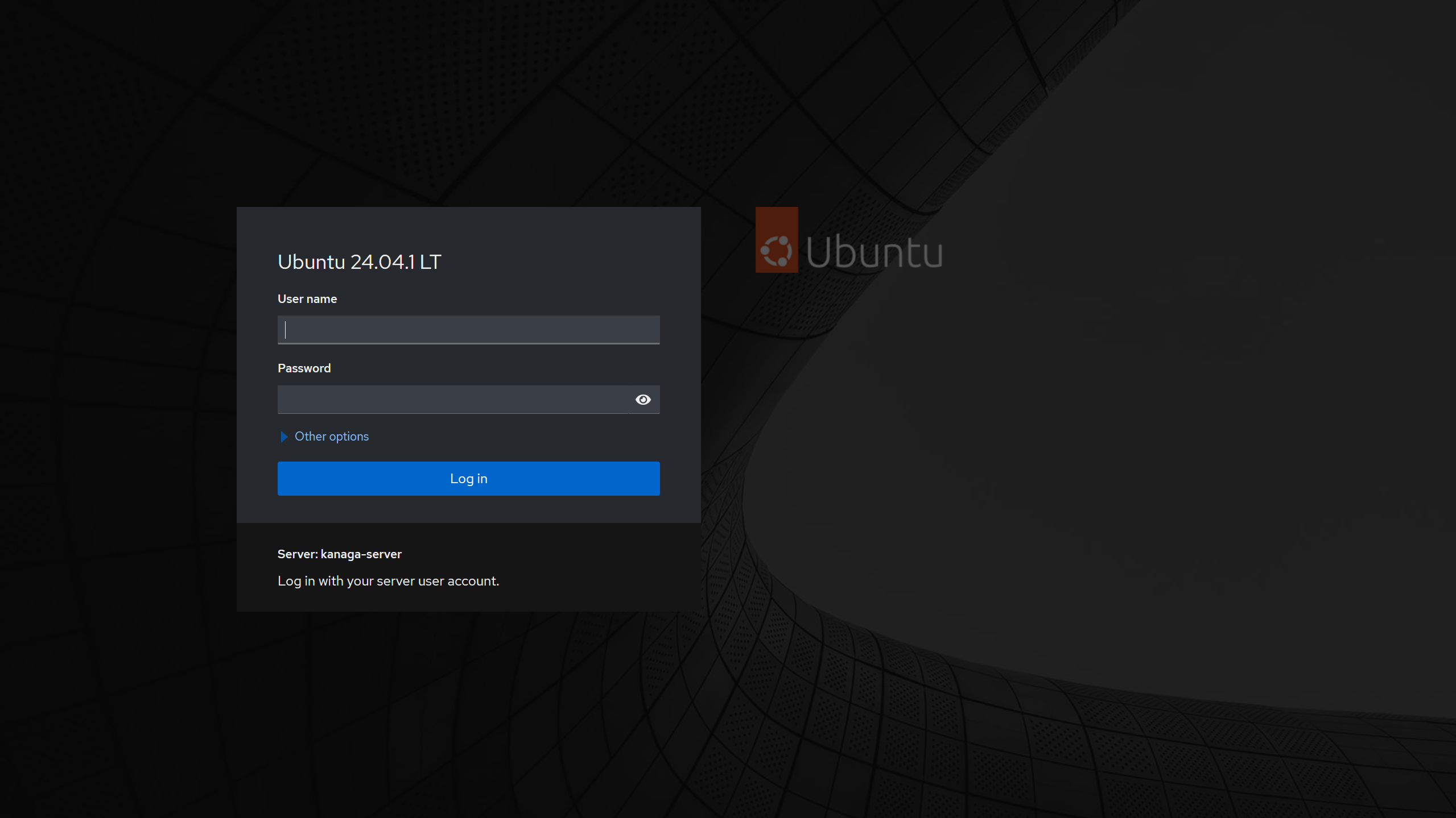 Figure 2. Illustration of the web portal of cockpit.
Installation and configuration of pfsense
Introduction
This part of the blog post explains how to set up a captive portal trough a LAN, this one will be used to grant access to internet to the local machines, due to limitations imposed by pfsense the default captive portal that use classical credentials (login and password) will be used.
Installation and Configuration of pfsense
I’m not going to document all steps to create a virtual machine via cockpit because the procedure is almost identical to the one described at the security onion section. However you have to notice that for creating the virtual machine you must select FreeBSD 14.0 as Operating system and adapt the default network interface by selecting Direct attachment as Interface type.
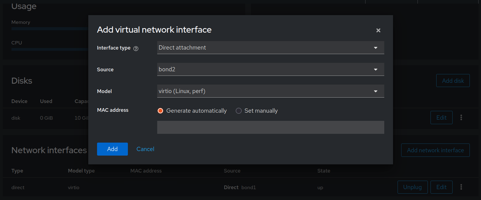 Figure 3. Illustration of the new interface added to the vm.
You’ll also need to add second interface, especially the third I was talking about earlier in this document, like the previous interface you’ll need to select Direct attachment as Interface type and Virtio (Linux, perf) as Model.
Once done you can start the machine and install the system, the installation has nothing particular so this one isn’t documented here.
After the installation you will need to specify what interface you want to use then by taping their name and confirm your choice, when done your 2 interfaces will get IPs, you can use one of them to get access to the login page of the pfsense. (Default credentials : login +> admin ; Password : pfsense)
Depending if you try to access to it via the LAN or the WAN if it doesn’t work you probably need to switch the network interface you want to access to by adapting your network parameter on the machine you use to get access to it.
When logged to pfsense for the first time, you’ll see welcome to pfsense software message where you’ll be invited to configure some parameters of the pfsense related to the WAN and LAN interface.
Configuration of the DHCP server
Now it’s time to work on the DHCP server of the architecture and the pfsense, to do that you can access to the parameters of the DHCP server by clicking on the DHCP Server available trough the Service menu in pfsense.
When you are in the menu you can enable the server by clicking on Enable DHCP server on LAN interface, then you can configure the address pool range in the Primary Address Pool section and add the DNS servers you want to use in the_Server Options_ section, finely in the Other DHCP options you can indicate the gateway that is the IP of your LAN interface in pfsense.
Once done you can click on Save (blue button, see bottom of the page), don’t forget to apply these change, you should normally see a button to apply these change on the top of the page. In this menu you also have the opportunity to add static DHCP mapping.
Creation of a user
Before setting up the default captive portal of pfsense we need to create a user that will be used to login in to it. If we want a captive portal that implement authentication with credentials that is compatible with our infrastructure we need to use the default captive portal of pfsense. Unfortunately pfsense doesn’t offer the possibility to create a personalize captive portal (with the version I used).
So to create a user you can navigate to System > User Manager and click on the Add green button, then you can defined a name (login) and password for the account to finely click on the Save blue button.
Once this one applied you can go trough the parameters of the user created click on effective privilege and select User - Service : Captive Portal login before saving.
Configuration of the captive portal
To configure the captive portal you can navigate to the Services menu and click on Captive Portal and then click on the green Add button. After that you can define a zone name (name of the captive portal) and a description.
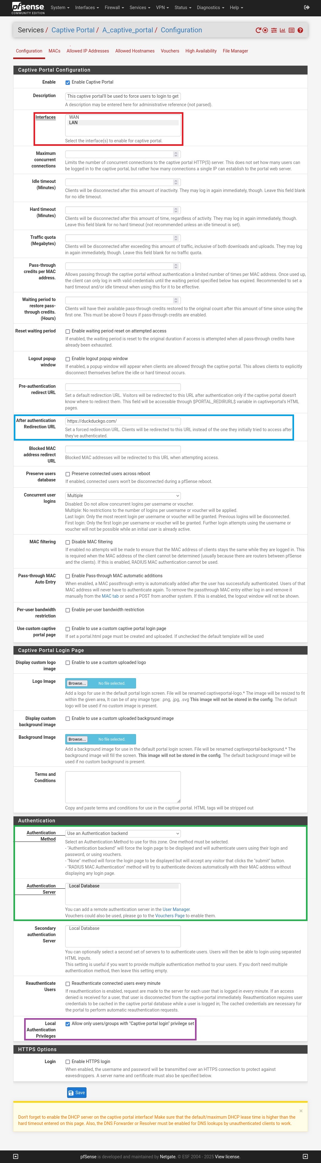 Figure 4. Parameters of the captive portal.
First you can enable this one by checking the Enable Captive Portal option on the top of the page, then you can select the LAN interface as the interface on which the captive portal will be applicated (see red outline on the figure 4), then you can fulfil the After authentication Redirection URL with the URL of a web page you want to redirect the user once logged to the captive portal (see blue outline on the figure 4).
In the Authentication section you must chose Use an Authentication backend as Authentication Method and select Local Database as Authentication Server (see green outline on the figure 4), these parameters are crucial because it defines the way the authentication works, here we specify that the captive portal must include champs for credentials and use it’s local database (where users on the pfsense are located) to verify if the credentials are correct.
You can also check the Local Authentication Privileges option (see purple outline on the figure 4) to allow local user(s) with the effective privilege set earlier to be able to login on the captive portal and finely you can click on the blue Save button at the bottom of the page to apply and save the change.
Now the captive portal had been set up when a machine on the LAN will attempt to get access to a resource over internet this one will be redirected to the captive portal.
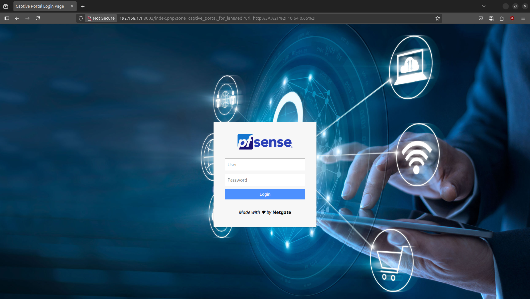 Figure 5. Captive portal of the pfsense with a personalize background.
Installation an configuration of security onion
Before reading this section you must know that several installation type are available for security onion, one requirements of this architecture is that one must be deployed in environment where access to critical resources such as electricity and internet are limited. So to satisfy these requirements a standalone installation type of security onion had been used, it means that all components that constitute security onion are present on the system installed.
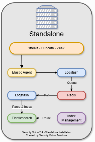 Figure 6. Representation of a standalone installation of security onion.
Configuration of the virtual machine
To create a KVM virtual machine you can go in the Virtual machines menu of cockpit and click on the Create VM button (see outline on the figure 18), then you will need to configure the following settings before clicking on the Create and edit button :
- Name
- Connection +> select System, this connection mode is designed for vm servers
- Installation type +> select Local install media (ISO image or distro install tree), a local ISO is used because we don’t have necessary a good internet connection.
- Installation source +> Path where the ISO file is located
- Operating system +> Unknown
- Storage +> Select Create a new qcow2 volume
- Storage limit +> It depends on your needs
- Memory +> It depends on your needs
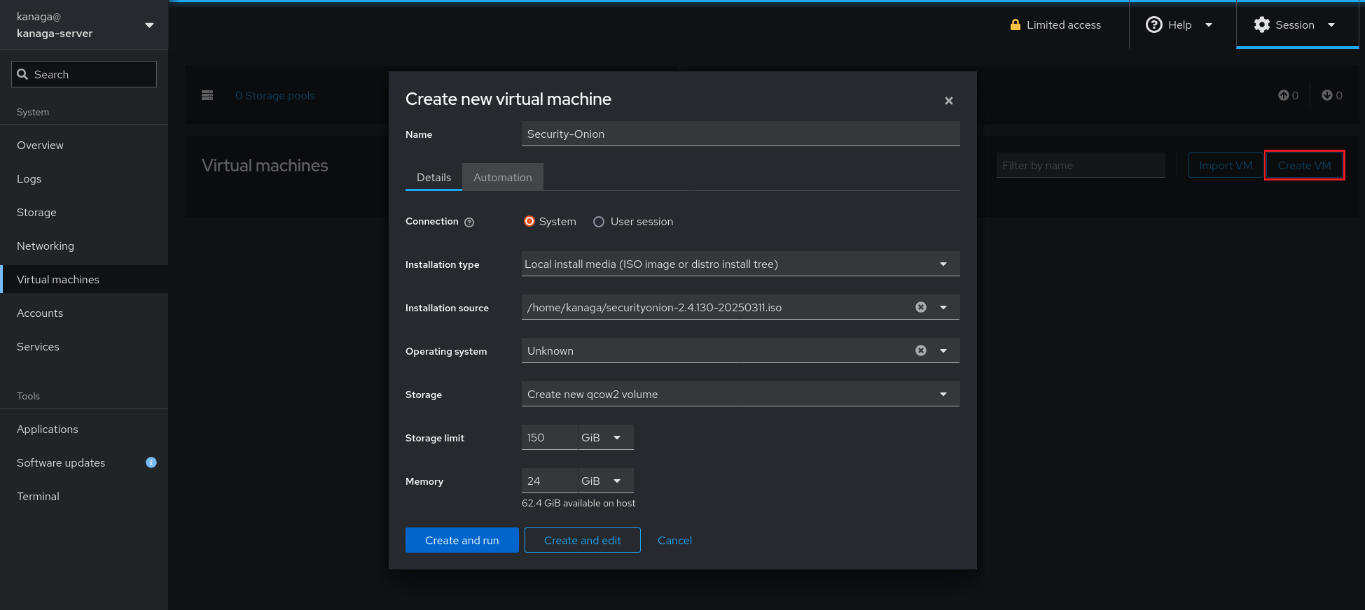 Figure 7. Menu used to create the security onion vm.
You could potently face some issues when creating the machine, if an error occurs about permissions it could be related to ISO file or it’s path that is used for the VM, if it is the case set the permissions read and execute for group and other via the chmod command.
After the vm created you can edit it by clicking on, via the Overview plane of the vm you can make that the vm meet the necessary hardware requirement by add the resources needed.
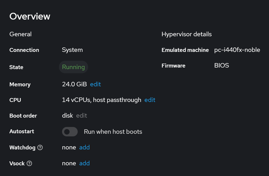 Figure 8. Overview of the vm created recently.
Security onion also need of 2 network interfaces to be installed, so you can scroll down to the Network Interfaces menu and click on Add network interface (see outline on the figure 9).
Then you can select the following parameters :
- Interface type +> Direct attachment
- Source +> Select one of the bond interfaces created during the installation of ubuntu server.
- Model +> virtio (Linux, perf)
- MAC address +> Generate automatically
- Persistence +> Checked
Direct attachment have been chosen as interface type because it links directly virtual machine’s NIC to a specified interface which is in this case a bond interface. By default the interface mode selected is bridge (for the vm created on the server), it means that packets destinations and origins that are on the same host machine go trough a macvtap device (driver) if the machines are both in bridge mode if either none are a VEPA (hairpin-capable) capable switch is required.
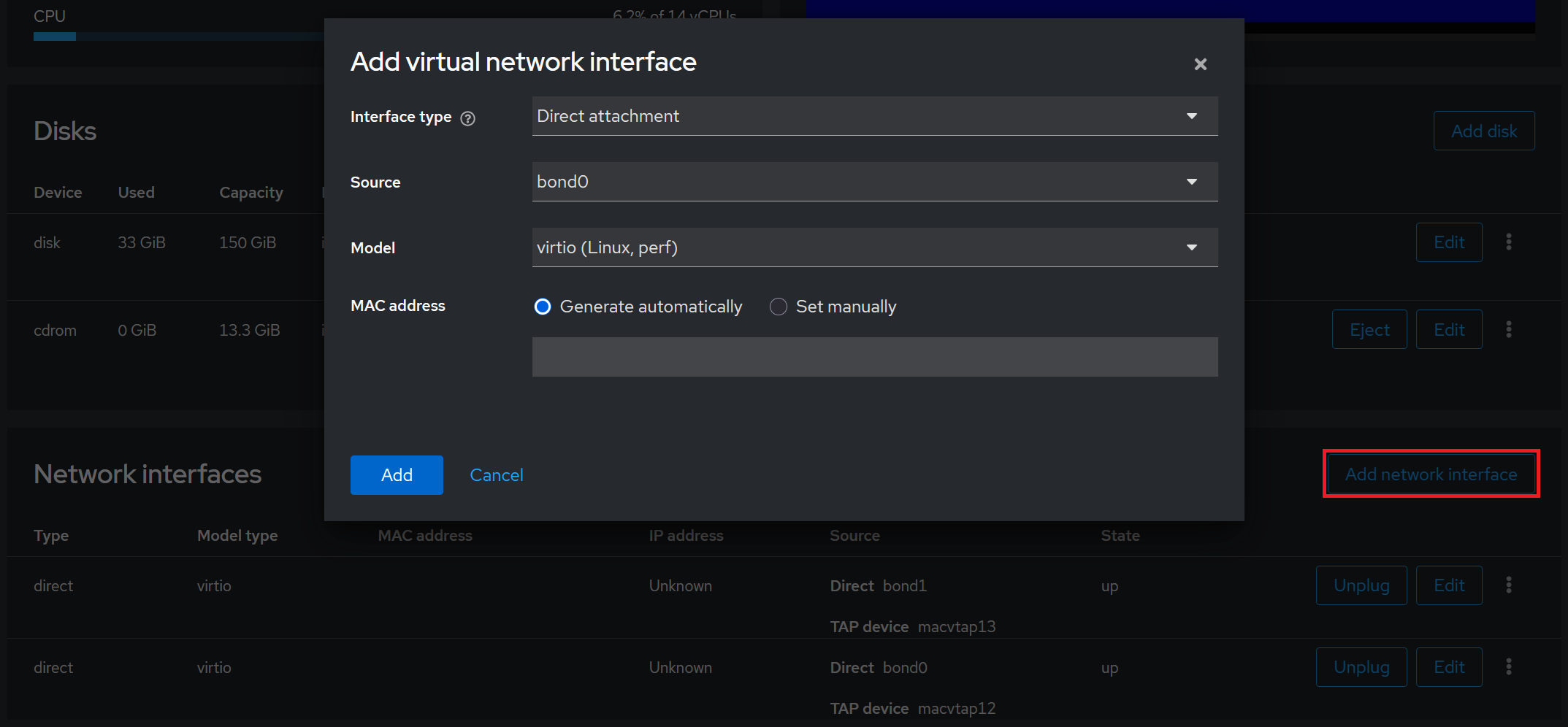 Figure 9. Menu used to add a virtual network interface.
Installation of security onion
Now it is time to start the machine by clicking on Run, then you just have to follow the different steps.
When the installation will be done with the IP of the machine you can use to access to the web interface. Once logged to the web interface of security onion you will face a kind of interface that should looks like the figure 10.
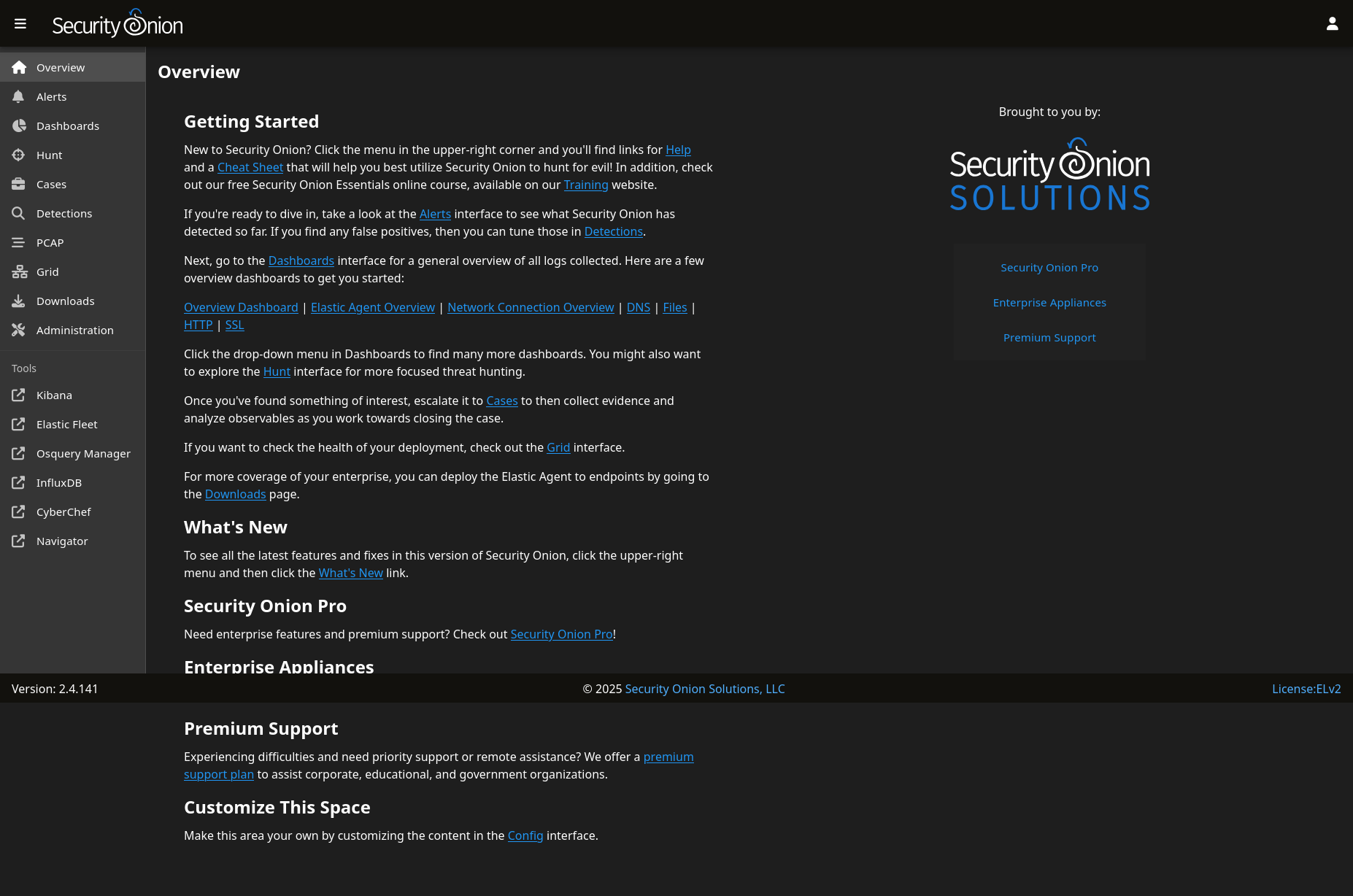 Figure 10. Security onion web interface once logged to it.
Installation an configuration of checkmate
Introduction
This section explains how to install checkmate on a server to implement global monitoring of the infrastructure.
Warning ! This part of the tutorial can requires an internet connection.
Before starting its recommended to get the IP address of your machine to get access to the web interface of checkmate.
Installation
To set up checkmate docker will be used, checkmate runs with containers so be sure to have installed docker before starting this tutorial.
If docker is already installed done you can download the docker file for checkmate with the following command :
wget https://raw.githubusercontent.com/bluewave-labs/Checkmate/refs/heads/master/Docker/dist/docker-compose.yaml
Then run checkmate by executing the following command in the directory where docker file is located : sudo docker compose up
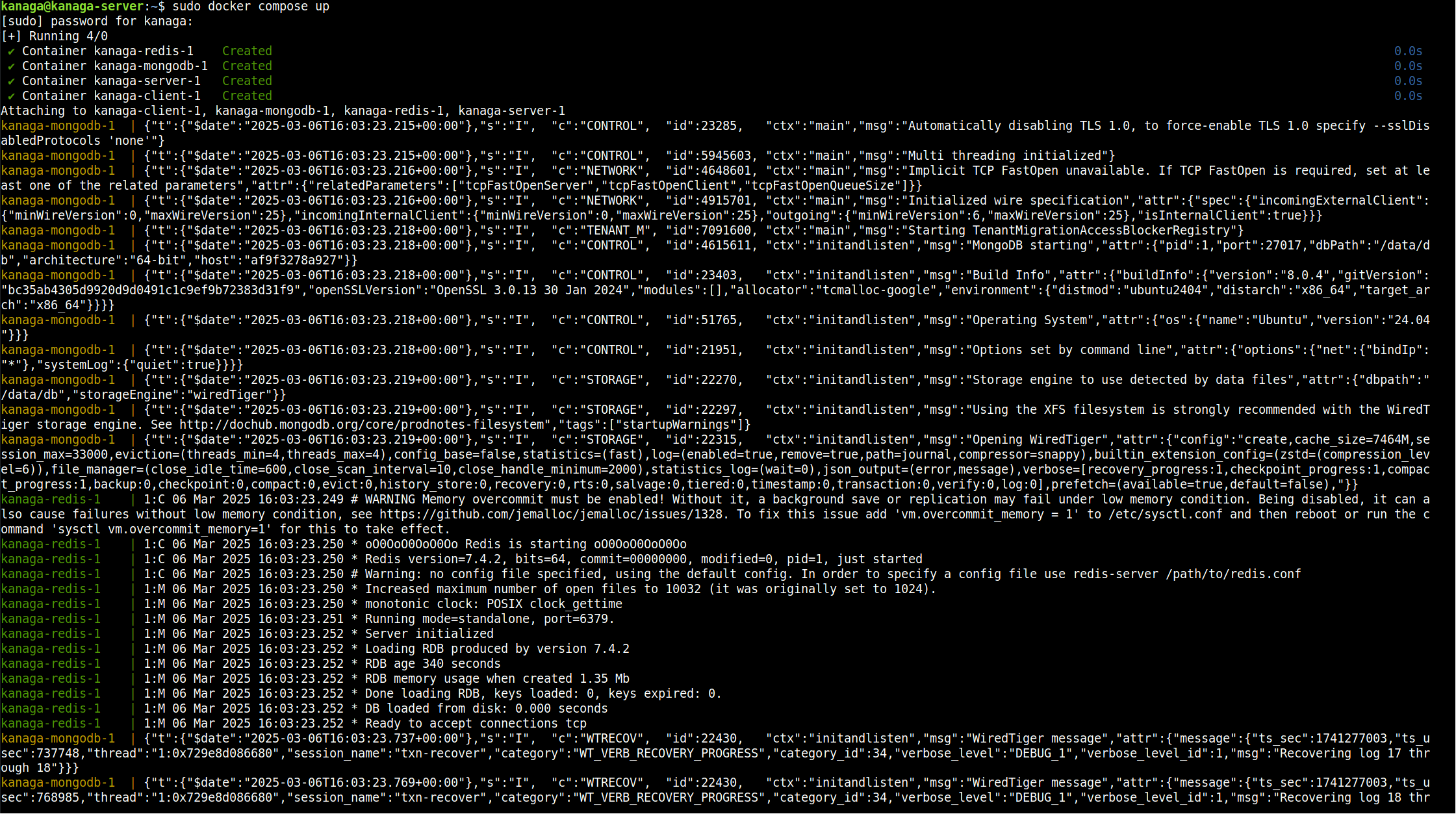 Figure 11. Illustration of checkmate that is setting up via the docker file.
Configuration
Once done you can open your web browser and reach the server via his IP address, if you can’t reach it just by indicating his IP address try to precise the port that have to be used, it is normally 5000. (ip_of_the_machine:5000)
The first time you reach the server (frontend part) you should see a register page if it is not the case modify the URL by adding /register at his end, then create an account. A name, surname, email address and password will be requested.
Then you can login to the server with the credentials chosen (via the /login page (in the URL (ip_of_the_machine/login for ex))).
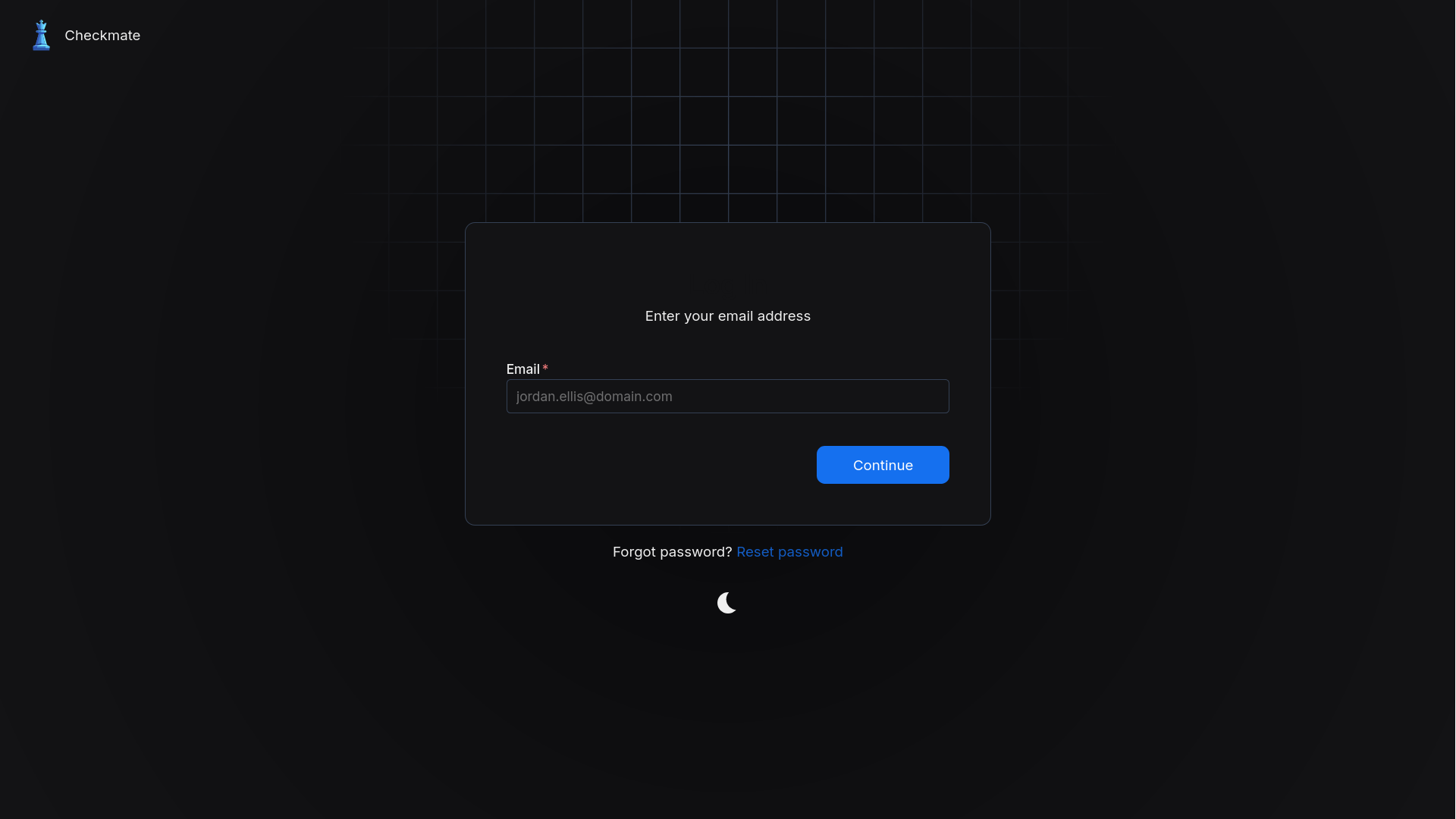 Figure 12. Login page of the server
When logged, you should see an interface similar to the figure 13, on the right side of it the following subsections are present :
- Uptime +> Used to monitor the availability of resource, this can be a device, a website, a container or a port.
- Pagespeed +> Used to monitor the page speed of website
- Infrastructure +> This subsection contains all devices monitored with the Capture agent.
- Incidents +> All incidents detected such as non availability of a resource are centralized there.
- Maintenance +> Menu that can be used to define maintenance period and avoid false error in the detection system.
- Account +> Settings related to the account used in checkmate.
- Settings +> Settings related to checkmate
- Other +> Documentation, API, changelog, etc
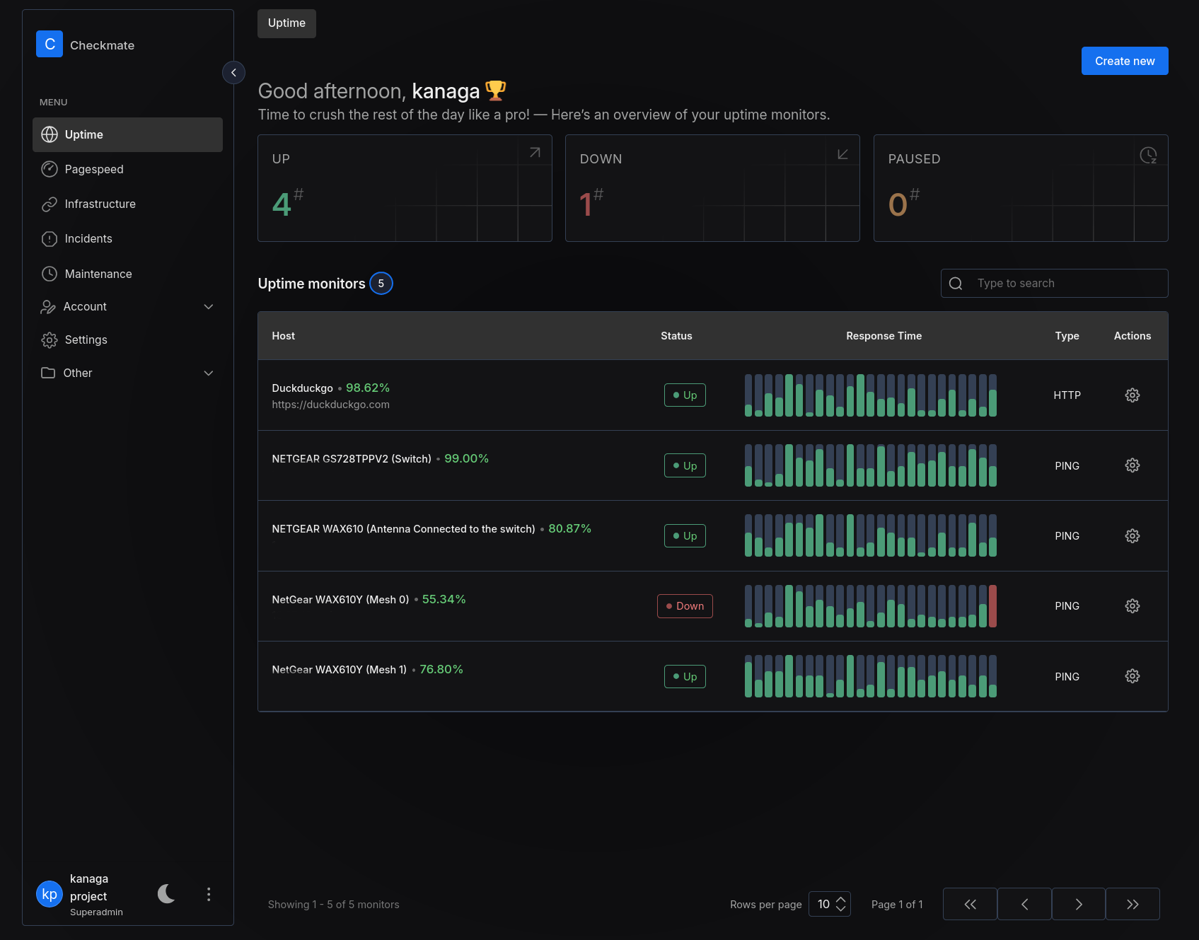 Figure 13. Uptime menu with resources added.
Infrastructure menu + installation of the agent
Checkmate also provides additionally a Capture agent that can be installed to get an overview on the machine(s) resources monitored.
To monitor a machine you will need to run the following command in a terminal to download the agent (Capture) and run it into a container (warning you’ll need of an internet connection):
docker run -v /etc/os-release:/etc/os-release:ro \
-p 59232:59232 \
-e API_SECRET=REPLACE_WITH_YOUR_SECRET \
-d \
ghcr.io/bluewave-labs/capture:latest
Once the container lunched you can go through the Infrastructure subsection of checkmate and click on Let’s create your infrastructure monitor or Create New, then you ill need to fulfill the following things :
- Server URL +> URL used to access to the metrics monitored ()
- Protocol +> HTTP is by default used by the agent
- Display name
- Authorization secret +> The key pass you chose before run the docker run command
- Frequency check
Configuration of the Wi-Fi mesh network on the NETGEAR antennas
This section describes how to create and configure a Wi-Fi mesh with the preinstalled module (firmware) on the NETGEAR WAX610 and WAX610Y antennas, it describes the technologies used and justify why a technology had been used instead of an other.
There’re several way to deploy a Wi-Fi mesh but here we are going to configure it with the preinstalled module of the antennas instead of using Insight App of NETGEAR because the mesh must be deployed within a environment that not necessary have an internet connection.
How to configure the antennas
First you must plug the WAX610 (the entry point node) on an electric supply to powered it on and to a network such as the switch of the architecture for example, you also need to power on a WAX610Y, don’t forget that these antennas are PoE (Power Over Ethernet).
Once done you must check the IP of the WAX610 to access the web portal interface, do the same for the WAX610Y via the Wi-Fi network it broadcast. (See the default password associated back to the antenna)
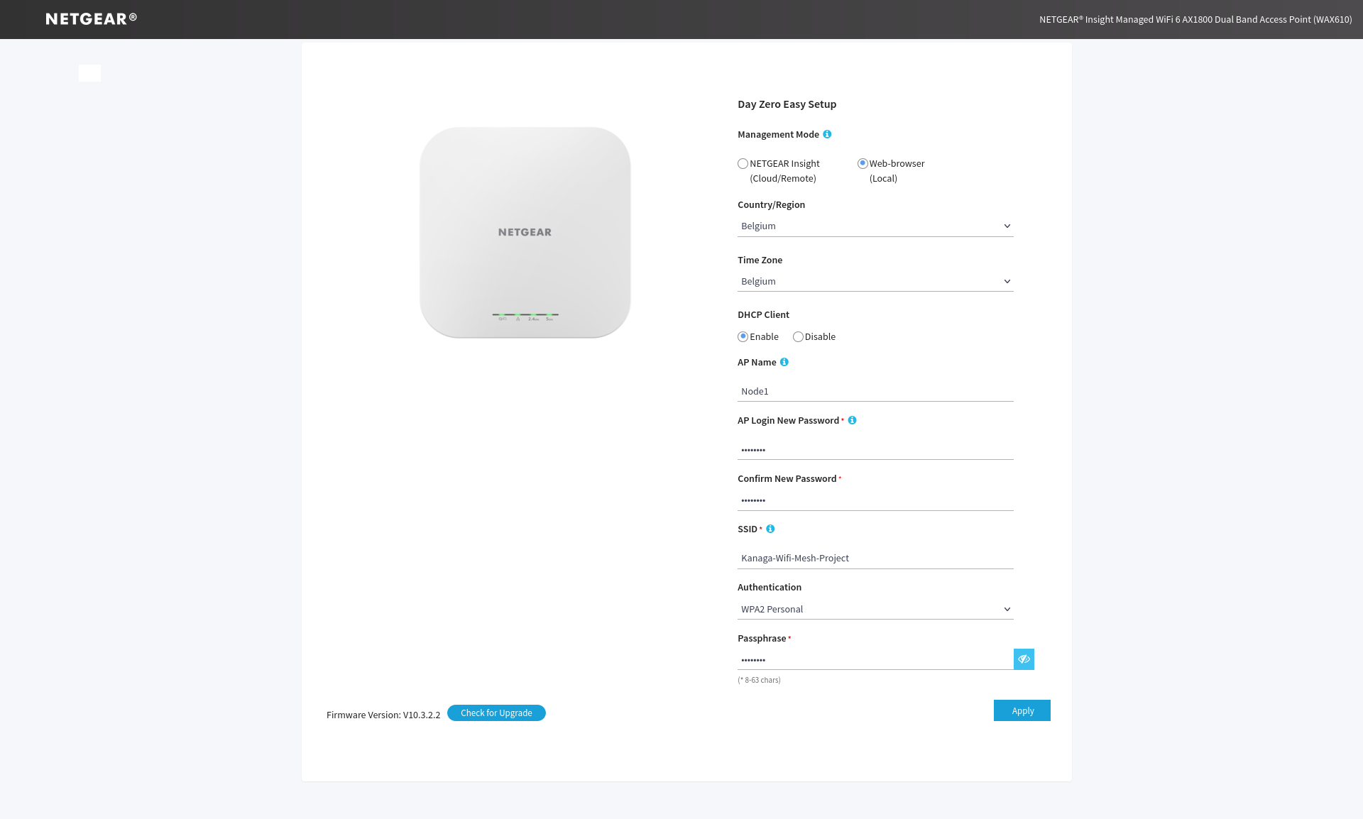 Figure 14. Web portal used to configure of the antenna.
The first time you join the web page of the antenna you will have to log into it with the default credentials (admin as the username and password as the password), when logged you will see the configuration page similar to the figure 14.
After that you must selection the Web-browser (local) option and complete the form depending on your needs once validate the devices will restart and apply the configuration. For this part just pay attention you must select WPA2 Personal as Authentication parameter because it’s the only one available security for setting up the Wi-Fi mesh on the antenna’s used.
These steps must be done on both apparels, the WAX610 and the WAX610Y, it is possible that these steps must be repeated if a device doesn’t apply correctly the modification.
Then, when the antennas have been rebooted you can connect to them via their Wi-Fi network broadcasted and log yourself to the web page login to get access the dashboard of the app.
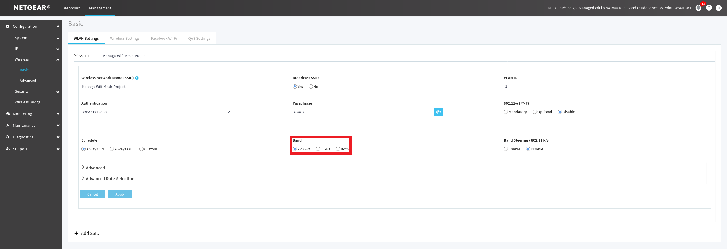 Figure 15. Basic options available to configure the Wi-Fi network of the antenna.
To configure the mesh you need to choose a band range for the mesh, I’ll use 2.4Ghz because it can cover a much large area and not all devices are compatible with 5Ghz band. To choose your you can go trough the Management menu then click on Configuration plane > Wireless > Basic > Wireless Settings (on the left) and finely choose your band as you can see on the red outline of the figure 15.
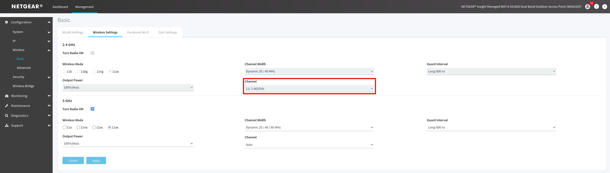 Figure 16. Advanced options to configure the Wi-Fi network of the antenna.
Another requirement before setting up a mesh is to set a channel for your band, I personally chose the 11th because its a non-overlapping channel, it will reduce the risk of interferences. To set it you must go trough the Management menu then click on Configuration plane > Wireless > Basic > Wireless Settings (on the left) and click on the Wireless Settings panel to finely chose your band as you can see on the red outline of the figure 16.
Once these steps are done you can go trough the Wireless Bridge menu accessible via the Configuration plane of the Management menu and roll out the WDS1 menu (see figure 17). Wireless bridge is a feature that can be used to merge 2 different networks together, it can also be used to set up our wifi mesh in this case.
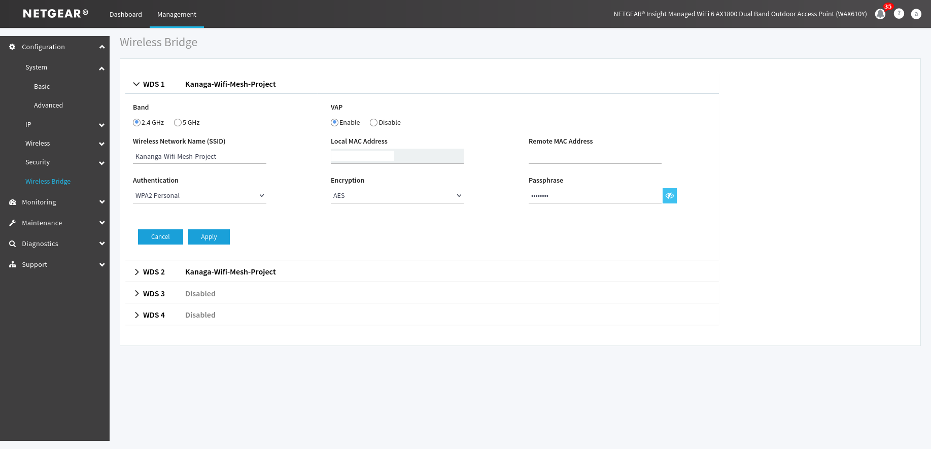 Figure 17. Settings to set up to establish the wifi mesh
On both antennas, WAX610 and WAX610Y you must in WDS1 enter the SSID and the MAC address of remote antenna with which you want to implement the mesh, you also must select the type of the authentication (WPA2 Personal in this case) and enter the password of it Wi-Fi network before saving. (Figure 17 illustrates pretty well this section)
When these steps will be done you check the status of the mesh by going trough the Monitoring menu of the Management menu and click on the Wireless Bridge menu and roll out the WDS1 pane. If a green link between 2 apparels is shown congratulation your mesh had been successfully deployed.
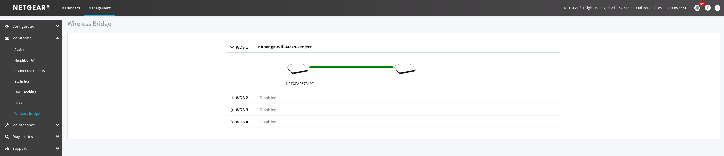 Figure 18. Status of the mesh established
Warning : If you don’t see any changes after applying the mesh parameters you will probably need to reboot the devices.
Adding extra antenna
To perform it you will need to follow the same steps described earlier in this document, pay attention that the way you configure the connection between each node describes also the way they communicate between each other on the area you want to cover.
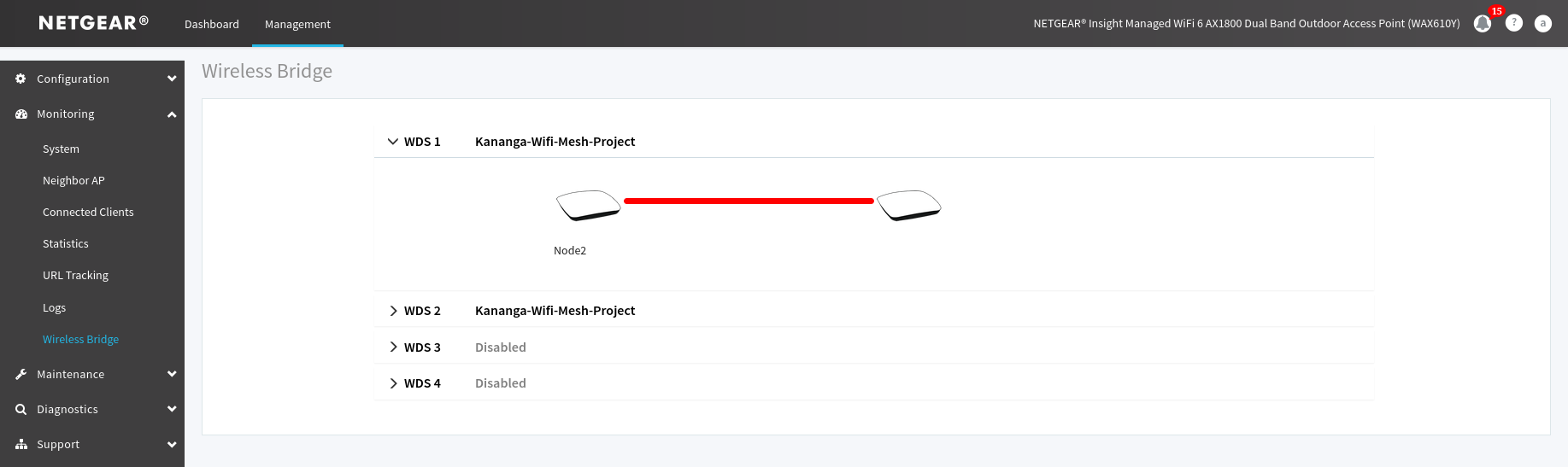 Figure 19. Illustration of the first mesh link crash due to the second mesh added.
If you notice that the first mesh link configured in the WD1 roll down menu is red (has crashed) in the monitoring menu dedicated to the mesh you will need to reboot the antenna to correct it, if the link is still red after that then you probably did a mistake in your configuration.
Testing action radius of the NETGEAR antennas
This section describes how the test had been handled to estimate the coverage area of a mesh in 2.4Ghz in different environment such as outdoor and indoor.
During the tests linssid tool had been used to measure the strength of the mesh signal, some resources available in the Bibliography section had been used to interpret signal strength during the test.
The limit to consider a Wi-Fi strength as good is around 70dm, this limit had been defined based on the documentation listed in the Bibliography section. 70dm is also considered as a good signal enough to surf on internet.
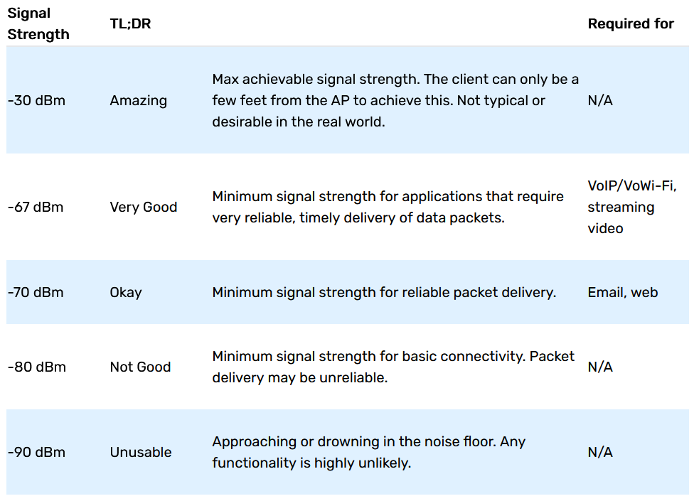 Figure 20. Table used to interpret the signal strength.
During all tests a NETGEAR WAX610Y plugged to a Mobisun Pro Air battery pack via a PoE injector have been used.
The estimations realized in the Indoor with separation and Indoor without separation tests have been done by counting how many foots I did between the access point and 70dm signal strength limit, to understand how the foots had been converted to meters please see the references mentioned in the Bibliography section.
This tests don’t take in consideration the composition of the separations (like walls for example), if you want to see the tool I used to convert my foots to meters please check the first source in the Bibliography section.
Outdoor test
This test had been realized in the “great yard” of the Royal Military Academy without any obstacles.
Once the test lunched I traced a parallel line to the access point and walk away from it until reaching the 70dm or being around it (signal can have variations).
Based on my measure the coverage area/radius of an antenna in this kind of environment is about 26 meters.
Indoor with separation
For this test the mesh had been placed into the middle of a hall at 3th floor of the building of the RMA after what I tried to walk away from it, based on my measure I can say the average radius is about 12 meters.
I did a second test by placing the mesh in the lab, closing the door and the result are almost identical to the first one. (some variations of the signal can appear).
A third test had been made by placing the mesh near of the stairs at the third floor after what I go down, the stairs, the result shown that the coverage was good (around 70 dm) with a distance of “one floor” under the exact position mesh, depending of where you’re in the building some variations can appear quickly.
It is recommended to place a mesh at the lower floor to ensure a good signal on a much bigger area.
Indoor without separation
During this test the mesh had been placed into a hall at 3th floor of the building of the RMA after what I tried to walk away in parallel from it, based on my measure I can say the average radius is about 15 meters.
Testing the endurance of the battery packs
This document describes how the endurance of a Mobisun Pro Air (230V / 300W / 154Wh / 40.000 mAh) battery pack had been tested.
Test environment set up and lunch of the test
The test environment was composed of a NETGEAR WAX610Y plugged to the battery pack with the solar panel faced on the table via a POE injector and a NETGEAR WAX610 plugged to a power supply and a switch on another.
To simulate network activity I created a shell script who’s the following :
#! /bin/sh

while true
do
	curl --location --remote-name https://mirror.jonas-prz.be/iso/2025.02.01/archlinux-2025.02.01-x86_64.iso // Download the ISO of arch linux
	rm archlinux-2025.02.01-x86_64.iso
	ping 8.8.8.8 -c 55 // Do 55 pings to 8.8.8.8 (google DNS server)
done
Details of my test are the following :
- 11/02/2025 at 10H34 AM +> The battery pack had been powered on.
- 11/02/2025 at 10H37 AM +> The shell script had been ran on a computer connected to the mesh.
- 11/02/2025 at 04H27 PM +> Break, the test is suspended. The battery had 26% of charge.
- 12/02/2025 at 09H05 AM +> The test had been relaunched in the same time than the script.
- 12/02/2025 at 10H00-5 AM +> The test was finished because the battery was empty.
To charge the last one from 0% to 100% it takes around 1H30.
Conclusion
The test of the battery is around 7 hours and a complete charge takes around 1H30.
Bibliography
YouTube. https://www.youtube.com/watch?v=pkP2kCcede0. Accessed 7 May 2025.
“05. WPA WPA2 Personal (PSK) Authentication.” GitHub, https://github.com/koutto/pi-pwnbox-rogueap/wiki/05.-WPA-WPA2-Personal-(PSK)-Authentication. Accessed 6 May 2025.
18.11. Attaching a Virtual NIC Directly to a Physical Interface | Red Hat Product Documentation. https://docs.redhat.com/en/documentation/red_hat_enterprise_linux/6/html/virtualization_administration_guide/sect-attch-nic-physdev#sect-attch-nic-physdev. Accessed 22 Apr. 2025.
20.16.9.6. Direct Attachment to Physical Interfaces | Red Hat Product Documentation. https://docs.redhat.com/en/documentation/red_hat_enterprise_linux/6/html/virtualization_administration_guide/sub-sub-section-libvirt-dom-xml-devices-network-interfaces-direct-attachment-to-physical-device#sub-sub-section-libvirt-dom-xml-devices-Network-interfaces-direct-attachment-to-physical-device. Accessed 22 Apr. 2025.
23.21. A Sample Virtual Machine XML Configuration | Red Hat Product Documentation. https://docs.redhat.com/en/documentation/red_hat_enterprise_linux/7/html/virtualization_deployment_and_administration_guide/sect-manipulating_the_domain_xml-a_sample_configuration_file#sect-Manipulating_the_domain_xml-A_Sample_configuration_file. Accessed 22 Apr. 2025.
Antil, Pradeep. How to Create LVM Partition in Linux (Step by Step). 16 Dec. 2021, https://www.linuxbuzz.com/create-lvm-partition-in-linux/.
Baekel, Roy van. Exhar/Linssid. 2014. 13 Jan. 2025. GitHub, https://github.com/Exhar/linssid.
Black. “Linux - How to Recursively Chmod a Folder?” Super User, 23 May 2018, https://superuser.com/q/1325221.
Captive Portal | pfSense Documentation. https://docs.netgate.com/pfsense/en/latest/captiveportal/index.html#. Accessed 7 May 2025.
“Cockpit Project.” Cockpit Project, https://cockpit-project.org/. Accessed 19 Feb. 2025.
CommandMasters. How to Use the Command “vgdisplay” (with Examples). https://commandmasters.com/commands/vgdisplay-linux/. Accessed 24 Feb. 2025.
Dahan, Marc. “How to Set up a Captive Portal on pfSense.” Comparitech, 25 Aug. 2023, https://www.comparitech.com/blog/vpn-privacy/captive-portal-pfsense/.
“EAPOL (Extensible Authentication Protocol over LAN).” NetworkLessons.Com Community Forum, 13 Nov. 2023, https://forum.networklessons.com/t/eapol-extensible-authentication-protocol-over-lan/40778.
FRSE, Prof Bill Buchanan OBE. “The Great WiFi and Password Protector: PBKDF2.” ASecuritySite: When Bob Met Alice, 30 Oct. 2023, https://medium.com/asecuritysite-when-bob-met-alice/the-great-wifi-and-password-protector-pbkdf2-92aa5802f2c4.
“GitHub - Security-Onion-Solutions/Securityonion: Security Onion Is a Free and Open Platform for Threat Hunting, Enterprise Security Monitoring, and Log Management. It Includes Our Own Interfaces for Alerting, Dashboards, Hunting, PCAP, Detections, and Case Management. It Also Includes Other Tools Such as Osquery, CyberChef, Elasticsearch, Logstash, Kibana, Suricata, and Zeek.” GitHub, https://github.com/Security-Onion-Solutions/securityonion. Accessed 11 Feb. 2025.
Hardware Requirements — Security Onion Documentation 2.4 Documentation. https://docs.securityonion.net/en/2.4/hardware.html. Accessed 12 Feb. 2025.
“How Do I Register Any NETGEAR Product in Insight?” NETGEAR KB, https://kb.netgear.com/000048438/How-do-I-register-any-NETGEAR-product-in-Insight. Accessed 7 Feb. 2025.
“How Do I Set up an Insight Instant Mesh Network?” NETGEAR KB, https://kb.netgear.com/000061304/How-do-I-set-up-an-Insight-Instant-Mesh-network. Accessed 7 Feb. 2025.
“How Do I Troubleshoot an Insight Device That Has a Waiting for First Connect Status?” NETGEAR KB, https://kb.netgear.com/000065137/How-do-I-troubleshoot-an-Insight-device-that-has-a-Waiting-for-first-connect-status. Accessed 7 Feb. 2025.
How To Change KVM Libvirt Default Storage Pool Location. Sk, 24 Feb. 2025, https://ostechnix.com/how-to-change-kvm-libvirt-default-storage-pool-location/.
How to Configure Captive Portal on pfSense Software? - Zenarmor.Com. 5 Mar. 2023, https://www.zenarmor.com/docs/network-security-tutorials/how-to-configure-captive-portal-on-pfsense.
“How to Manage KVM Virtual Environment Using Command Line Tools in Linux.” GeeksforGeeks, 28 Dec. 2022, https://www.geeksforgeeks.org/how-to-manage-kvm-virtual-environment-using-command-line-tools-in-linux/.
“IEEE 802.1X Authentication Methods Compared.” Cloud RADIUS, 12 Sept. 2024, https://www.cloudradius.com/ieee-802-1x-authentication-methods-comparison/.
Johorcse. Security Onion: A Linux Distro For IDS, NSM, And Log Management | Unixmen. 12 Feb. 2025, https://www.unixmen.com/security-onion-linux-distro-ids-nsm-log-management/.
Kaliski, Burt. PKCS #5: Password-Based Cryptography Specification Version 2.0. Request for Comments, RFC 2898, Internet Engineering Task Force, Sept. 2000. IETF, https://datatracker.ietf.org/doc/rfc2898/.
Kiarie, James. How to Install KVM on Ubuntu 22.04 Step-by-Step. 24 May 2022, https://www.linuxtechi.com/how-to-install-kvm-on-ubuntu-22-04/.
—. Managing KVM Virtual Machines with Cockpit Web Console in Linux. 5 Jan. 2021, https://www.tecmint.com/manage-kvm-virtual-machines-using-cockpit-web-console/.
Kumar, Pradeep. Create and Manage KVM Virtual Machines via Command Line. 25 Oct. 2021, https://www.linuxtechi.com/create-manage-kvm-virtual-machine-cli/.
“Linux Directory Structure.” GeeksforGeeks, 16 May 2021, https://www.geeksforgeeks.org/linux-directory-structure/.
Longueur d’un pas en fonction de la taille: les chiffres | Objectif Plein Air. 13 Apr. 2023, https://objectifpleinair.com/longueur-pas-fonction-taille/.
“NETGEAR WAX610 USER MANUAL Pdf Download.” ManualsLib, https://www.manualslib.com/manual/1865056/Netgear-Wax610.html. Accessed 7 Feb. 2025.
Noh, Jaewon, et al. “Secure Authentication and Four-Way Handshake Scheme for Protected Individual Communication in Public Wi-Fi Networks.” IEEE Access, vol. 6, 2018, pp. 16539–48. IEEE Xplore, https://doi.org/10.1109/ACCESS.2018.2809614.
Pierce, Michelle. WiFi Signal Strength: A No-Nonsense Guide. https://techgrid.com/blog/wifi-signal-strength. Accessed 12 Feb. 2025.
“Security Onion.” Wikipedia, 7 Sept. 2024. Wikipedia, https://en.wikipedia.org/w/index.php?title=Security_Onion&oldid=1244508041.
Security Onion Documentation — Security Onion Documentation 2.4 Documentation. https://docs.securityonion.net/en/2.4/index.html#. Accessed 11 Feb. 2025.
Security Onion Solutions. https://securityonionsolutions.com/. Accessed 11 Feb. 2025.
Standalone Security Onion, a Perfect SIEM Solution for Small Networks | Cylab.Be. https://cylab.be/blog/338/standalone-security-onion-a-perfect-siem-solution-for-small-networks. Accessed 12 Feb. 2025.
Themefisher. How to Extend and Reduce a Volume Group in LVM. 18 Nov. 2020, https://www.thegeeksearch.com/how-to-extend-and-reduce-a-volume-group-in-lvm/.
Times, G. B. “How to Read Wifi Signal Strength?” GB Times, 27 Nov. 2024, https://gbtimes.com/how-to-read-wifi-signal-strength/.
Tucakov, Dejan. “How to Format Disk Partitions in Linux {ext4, NTFS and FAT32}.” Knowledge Base by phoenixNAP, 2 Dec. 2020, https://phoenixnap.com/kb/linux-format-disk.
Tutorial: Use the Linux OpenVPN 3 Connector Integrated with Cockpit. https://openvpn.net/cloud-docs/tutorials/configuration-tutorials/connectors/operating-systems/linux/tutorial--use-the-linux-openvpn-3-connector-integrated-with-cockpit.html. Accessed 24 Feb. 2025.
Velocenetwork. “What Is a Virtual Access Point? Complete Guide.” Veloce, 19 May 2023, https://www.velocenetwork.com/tech/what-is-a-virtual-access-point/.
Vgcreate Command Examples in Linux [Cheat Sheet] | GoLinuxCloud. 30 Jan. 2022, https://www.golinuxcloud.com/vgcreate-command-in-linux/.
WAX610 Admin Login Page Is Blank. 13 Apr. 2021, https://community.netgear.com/t5/Business-Wireless/WAX610-admin-login-page-is-blank/td-p/2083842.
“What Is a Virtual Access Point (VAP)?” JumpCloud, https://jumpcloud.com/it-index/what-is-a-virtual-access-point-vap. Accessed 13 Apr. 2025.
“What Is a Wireless Bridge?” NETGEAR KB, https://kb.netgear.com/227/What-is-a-wireless-bridge. Accessed 7 Feb. 2025.
“What Is Wireless Bridge Mode and How Do I Set It up on My NETGEAR Router?” NETGEAR KB, https://kb.netgear.com/24105/What-is-wireless-bridge-mode-and-how-do-I-set-it-up-on-my-NETGEAR-router. Accessed 7 Feb. 2025.
“Why Can’t I Monitor or Manage My Insight Managed Switch or Access Point in Insight ?” NETGEAR KB, https://kb.netgear.com/000044339/Why-can-t-I-monitor-or-manage-my-Insight-Managed-switch-or-access-point-in-Insight. Accessed 7 Feb. 2025.
“Wi-Fi Signal Strength Basics.” MetaGeek, https://www.metageek.com/training/resources/wifi-signal-strength-basics/. Accessed 12 Feb. 2025.
https://www.sonicwall.com/support/knowledge-base/overview-of-wireless-virtual-access-point-vap/170505810128245. Accessed 13 Apr. 2025.
This blog post is licensed under
CC BY-SA 4.0


- Pfsense
- Security Onion
- Checkmate
- Installation of the operating system
- Installation and configuration of KVM
- Installation of cockpit
- Installation and configuration of pfsense
- Installation an configuration of security onion
- Installation an configuration of checkmate
- How to configure the antennas
- Adding extra antenna
- Outdoor test
- Indoor with separation
- Indoor without separation
- Test environment set up and lunch of the test
- Conclusion